The guideline from the first page is echoed in this:
Lego parts are fundamentally made to fit together: dimensions can be derived by reasoning on simple constructions.
After determining the basic dimensions of 8mm×9.6mm and the 0.1mm play, we need to find these measures which constitute the next important set:
the height and diameter of the knobs
the diameter of axles
the diameter and placement of the axle bearings in Technics beams
the effective bearing length
the placement of the knobs on direction changers
the dimensions of Technics gears
Ideally, each of them should be found by linking it in some way to the basic dimensions.
Knobs
We start from the fact that the horizontal design spacing of knobs is exacty 8mm.
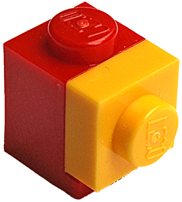
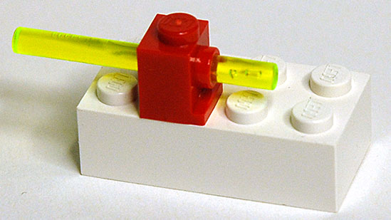
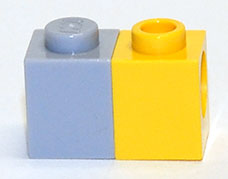
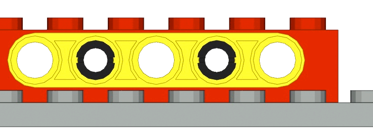
We observe this assembly:
an “illegal” plate and a brick placed diagonally
If you place the red 1×1 brick carefully at 45º you will still see light pass between its vertical edges and the sides of the adjacent knobs. The diagonal of the brick is very slightly smaller than the gap between knobs.
But the “illegal” yellow plate is firmly stuck between two rows of knobs. (“Illegal” means that the construction is “not according to the books” which is of course open to interpretation. You are not supposed to wedge plates between knobs. It’s “not done”.)
We know that the height of the plate is exactly 3.2mm, and since it sticks between the knobs, the gap between knobs must be very slightly less than 3.2mm. But the distance between knob centres is 8.0mm, which is the plate thickness plus a knob radius on either side; 8.0−3.2=4.8=2×radius=diameter). From this we can conclude that the diameter of the knobs must lie between 4.8mm and 4.9mm. Let us first exlore the hypothesis that it is 4.8mm, and the 1×1 brick is 8.0mm wide. In the two drawings below the stroke of the shapes is inside, i.e. the dimensions given include the thickness of the lines.
The edges of the 8.0mm brick clearly overlap the knobs of 4.8mm and the 3.2mm plate does not appear to stick. But if instead we take 4.9 and 7.8 then it looks much better:
Now the plate certainly “sticks” and the brick does not touch the knobs.
The diameter of a knob is 4.9mm — measured and computed
The height of a knob is more difficult to derive; measurement gives consistently 1.8mm either for knobs with no word “lego” embossed on them or measured outside the text when embossed. Over the text they seem to be 1.9mm high.
The height of a knob is 1.8mm — measured
I could not think of a construction in which the height of a knob is unambiguously related to the pitches.
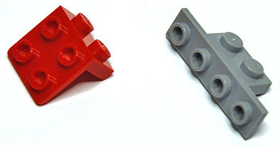
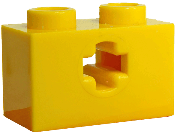
Direction Changer Knob Placement
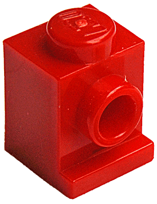
Some parts have knobs on their sides to allow the direction of building to be changed by a right angle:
direction changers
Where are the knobs on the vertical faces? Take a 1×1 brick with a knob on each face and consider this assembly, in which two of its vertical faces and its top are used to hold three small plates:
three plates fitted to a 1×1 brick with front knobs
All plates touch with no gaps: their bottoms and sides are flush with other planes. The knobs on the vertical faces must therefore sit in the centre of a square of 7.8mm×7.8mm flush with the top, i.e. it is 7.8mm/2=3.9mm from the top and hence 9.6mm-3.9mm=5.7mm from the bottom, exactly (if I am right about the play of 0.1mm).
There is an even smaller example that leads to the same conclusion: the “lantern” (part 4070).
a small direction changer
Put a 1×1 plate on it:
with a 1x1 plate
One expects the plate’s sides to be flush with the brick’s sides and top. Therefore the knob should be at half the plate width from the top: 7.8mm/2=3.9mm.
And then its centre is 5.7mm from the base of the brick.
Axles and Bearings
I have not found an easy way to link the diameter of an axle to the basic pitches.
Axles must turn freely in the bearings, but with little play. Best measurements of axles show 4.8mm consistently for their diameter. That turns freely in a 4.9mm hole.
The diameter of an axle is 4.8mm — measured
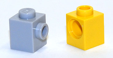
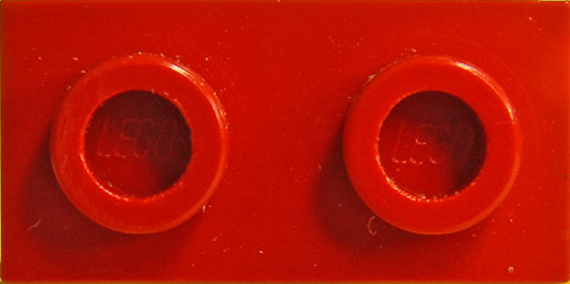
Knobs are 4.9 in diameter, and they do fit in the holes of axle bearings, albeit tightly.
knobs in bearing holes
If a bearing hole diameter is 4.9mm, the tightness of its grip on a knob can be explained by the fact that knobs normally are held only at a few points around their rim (usually three) whereas a bearing hole grips a knob along its whole circumference.
The diameter of a bearing hole is 4.9mm — derived from that of a knob
More on diameters of bearing holes
How big are these holes really? It is difficult to measure them with calipers because the fingers have a certain thickness which causes a slight error when pressed against a concave surface. Another way of measuring them is to insert two axles and measure at which distance they can be made to touch without forcing them to do so, then apply some trigonometry:
touching axles
This method is fraught with problems: firstly one has to be sure the axles are very straight, which the longer ones are generally not; secondly one has to turn the axles so that the “cross” figure cross section lines up correctly otherwise the angles will be wrong; thirdly it is not easy to determine the length at which the axles are just touching but not forced together.
The internal length of an axle bearing hole is difficult to determine too because there is a counterbore at each side. That turns out to be 6.2mm in diameter and 0.8mm deep(*). In the figure below the red trapezium and the dotted green rectangle indicate how to get the angle over which the axles are turned. I’m skipping the trigonometry here, but the diameter of the holes can be calculated from the angle of the axles, the distance at which they touch and the length of the hole (it does involve solving a quadratic equation).
Using this method with several trials, the diameter of a bearing hole is indeed close to 4.90mm.
* the effective bearing length is always 6.2, but the counterbore is 0.9mm deep in beams, as they are 8.0mm wide whereas bricks have the usual 7.8mm width allowing for play. The peg ring is somewhat wider than 1.6mm, again allowing for the play between bricks and no play between beams.
Technics Bearing Placement
This is arguably the most difficult to determine dimension: how high above the base is the centre of the bearing hole of a Technics brick?
Where would be a reasonable place?
Considering a bearing in a 1×1 brick, where would the centre “logically” go? Possibly at the centre of a square that fits either at the top or at the bottom of the rectangle that makes the front of the 1x1 brick:
But as bearing bricks have multiple bearing holes, and they must be 8mm apart, one could take a square of 8mm×8mm, the conceptual width of the brick, and set it at the top of the brick: the red square in dotted outline. Its centre is at 4mm from its top, hence at 5.6mm above the base. Or we could use the blue dotted line square, which sits at the bottom. In the first case the centre is 5.6mm above the base, in the second only 4.0mm.
It might even go in the middle between top and bottom, at 9.6mm/2=4.8mm.
Clearing knobs
An axle is 4.8mm in diameter and a bearing hole 4.9mm. A bearing hole at 4.0mm would put the bottom of an axle of 4.8 at 4.0mm−4.8mm/2=1.6mm from the base, and thus the axle would not clear the 1.8mm high knob of a brick in front of it.
At 5.6mm it clearly would.
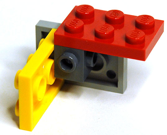
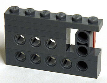
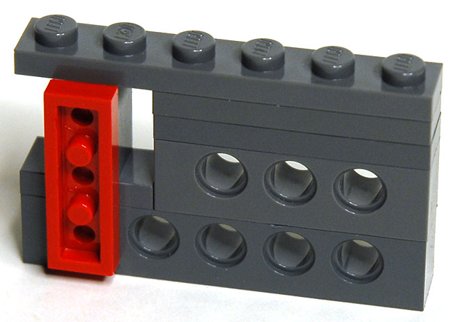
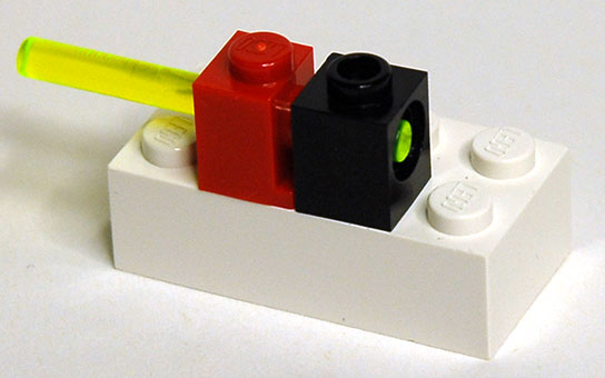
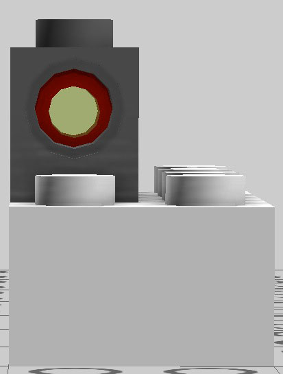
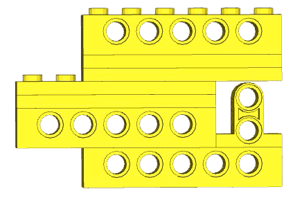
But look at this assembly, in which a special vertical bearing brick appears:
the special bearing brick under a platefrom the back, with a red plate
The special brick on top of a normal Technics bearing brick gives us a series of three holes in a vertical line with 8mm distances, so the vertical red plate fits exactly. But there is almost no clearance between the top of the special brick and the bottom of the plate above it: it is barely 0.1mm.
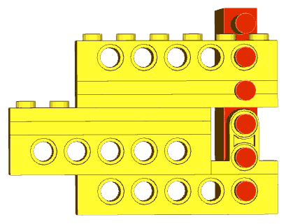
In the drawing below the special brick is coloured yellow. It is a strange brick in the sense that its width is only 7.4mmm whereas other beams are sometimes as wide as 7.8mm. At 7.4mm there is a gap of 0.1mm between its round top and the bottom of the plate covering it. Careful measurement gives:
From which I conclude that the Technics axle holes are at 5.8mm from the bottom of the bearing bricks. If it were any greater the round top part of the yellow brick would be too thin.
The centre of a Technics bearing is 5.8mm above the base of the bearing brick — measured and computed
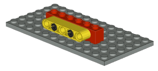
Then there are these constructions:
clearing a knobclearing a knob
In both cases the knob is a hollow knob which is not embossed with the word “lego” and thus only 1.8mm high. The axle clears it just. In the drawing below the dotted red circles indicate where the axle holes would be if their centres were at 5.7mm, showing that the axle in that case would not clear the knob, whereas the 5.8mm placement (with the axle shown) does.
The bearing hole height of 5.8mm is very slightly different from the 5.7mm height of the front knob on direction-changing bricks.
More evidence in favour of 5.8mm
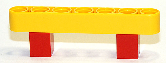
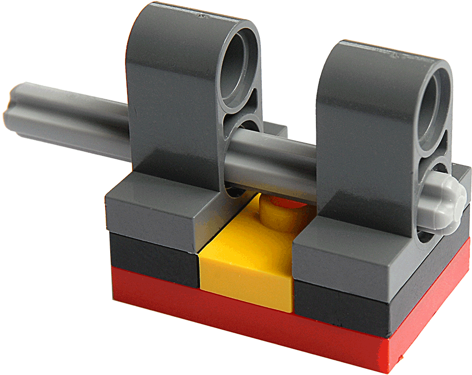
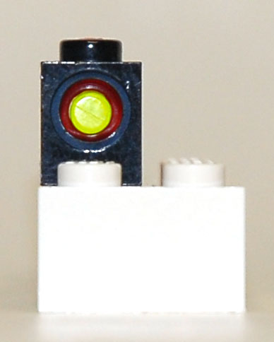
Is there really a difference of 0.1mm between the height of a Technics axle hole and a front knob? Yes. Make the following two assemblies, very carefully, and observe them closely; first:
a bar in a front-knob brickwith a Technics bearingseen head-on
The last photo was difficult to make, requiring careful alignment of object and camera, but you can see that the axle hole centre is indeed slightly higher than that of the bar.
Secondly:
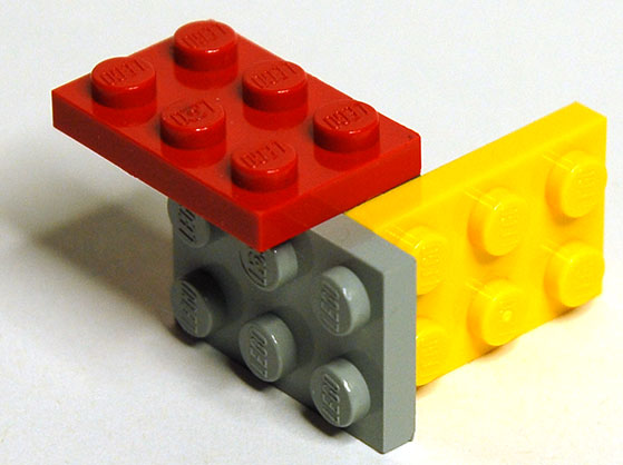
a front-knob brick and a Technics brickfitted together
The assembly is not exactly flush with the surface, the grey brick is lifted “off” by 0.1mm, which causes the combination to tilt slightly. Highly exagerated, what you see in the photo above is:
The 5.8mm value is not very important. If all axle holes were displaced vertically by a certain amount, all gears and wheels would still work in exactly the same way as they do now, because the relative distances between holes would not change.
As far as I know only two items would be influenced: the round top of the special brick with the two vertically arranged bearings, and the clearing of the knob by an axle.
However, those two items are the only reasons I can think of for the choice of 5.8 over 5.7. Both measures are also present in Lego’s own Lego Digital Designer (LDD) program and you can use LDD to make a virtual copy of the front knob brick and the Technics bearing to observe the same difference of 0.1mm:
the front-knob brick + Technics brick as done with LDDthe front-knob brick + Technics brick as done with LDD
Yet another argument
In “Stressing the Elements” Jamie Berard puts forward the argument that The Center Point was moved up in order to accommodate the additional plastic needed around the Technic hole so that a stud can still fit in the bottom of the brick.
Berard's document is excellent and I recommended reading it, but that argument is probably not true. If it is true, then it was totally unnecessary.
For normal Technics bearing bricks there is no problem at all: the knobs are between the bearings and there is plenty of space.
The worry of accommodating the knob then only applies to the few bricks where there is a bearing directly above a knob, as in the 1x1 brick or the 1x2 brick with two holes (I don't know of any other ones where a knob can sit directly under a bearing).
An axle hole is 4.9mm in diameter. There needs to be sufficient plastic to prevent deformations with axles under load, but not an awful lot. Let us use the word sleeve for the tube of plastic in which the axle turns. It has a certain wall thickness.
Begin by measuring the real clearing for those two bricks: in the 1×1 there is 2.3mm space to accommodate a knob; in the 1×2 it is 2.7mm!
By contrast, the clearing in a normal plate (3.2mm thick) is 2.0mm or 2.1mm at most.
The figure shows outlines for a 1×1 brick with the centre set at 5.8mm and a wall thickness of 1.05mm as well as a red dotted outline of a knob fitting under it, and for comparison a 1x1 plate next to it.
There is at least 0.2mm more space for a knob under the 1×1 brick than under a classic plate, and at least 0.1mm more if the centre of the bearing hole were brought down by 0.1mm to the more logical height of 5.7mm.
Some further considerations
In a normal Technics bearing brick, where the axle holes are between the knobs, the wall thickness of the sleeve at its top is 9.6 - 5.8 - (4.9/2) = 1.35mm.
In the bricks that worry us, the thickness of the sleeves at their bottom is 5.8-(4.9/2)-2.3=1.05mm and 5.8-(4.9/2)-2.7=0.65mm respectively.
In a normal brick the sleeve is no thicker than 5.8-(4.9/2)-2.4=0.95mm at the bottom. The 2.4mm clearing there is very difficult to measure because of the presence of the little studs; it can be done by carefully filing a piece of metal or plastic to fit exactly in the space, and then measuring its height.
Observe the first of the three figures below: if the hole sits 3.8mm from the top (5.8 from the bottom), the diameter of the sleeve can at most be 2×3.8=7.6mm which still leaves 9.6-7.6=2.0mm for accommodating a knob, which is sufficient though tight because of the embossing on top of knobs.
But the outer diameter of the sleeve does not need to be larger than 7.4mm, as shown by many beams. That would leave an extra 0.1mm without compromising anything. And even a lot less plastic around a hole would still mechanically work: note that the newer standard 2x4 brick has walls that are only 1.5-0.3=1.2mm thick.
The 1×1 and the 1×2 bricks where a bearing can sit just above a knob were likely designed later than the normal Technics bearing bricks. They would have shown a local flattening if there had not been enough space with a hole centre at 5.7mm from the bottom but still a real need for a thick sleeve: see the second of the three drawings above as a possible implementation.
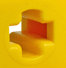
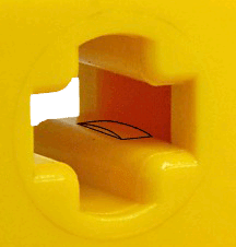
There are other instances of such small adaptations: in the lantern (part 4070) mentioned earlier the plastic just above the "lip" under the knob on the front face is actually zero thickness and depending on the mould the 4070 came from, one can even see through a narrow slit of missing plastic (as is in fact the case in the photo in the Direction Changer Knob Placement section on this page). That is because the front face is set back sufficiently that there is nothing left at just that point. But it does not compromise the strength of the brick or its ability to fit others.
So 5.8mm instead of 5.7mm came probably early on, and independent of anything else, but 5.7mm is the natural choice since it places the centre at the centre of the square that fits at the top of the 7.8x9.6mm rectangle. My strong conviction is that someone at the mould factory goofed by 0.1mm, and then it was too late. Thousands of sets may have been sold before it was spotted. The same happened with the curved Duplo rails, and there the moulds have been corrected only recently.
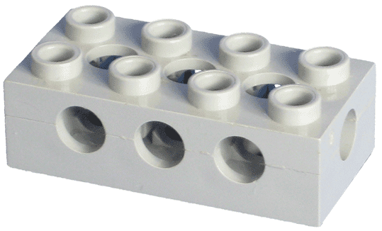
But the most convincing evidence that 5.8mm was not the result of moving the centre up to accommodate the knob is that even in normal bearing bricks the sleeve is only 7.0mm in diameter. In the photo below I drew evenly spaced red rectangles of 7.0×4.8mm over the sleeves.
bottom view of a 1×8 Technics bearing brick
The outermost ones do not exactly line up with their corresponding sleeves because of the perspective skewing of the photo. However it is clear that there is a 1.0mm gap between the sleeves. This can also be measured with some difficulty by carefully filing a piece of wire e.g. from a paper clip, until it inserts easily between cylinders and then measuring the thickness of the wire. The third drawing above repeats the earlier one; it shows a 1×1 brick with in red dotted line a 7.0mm cylinder, set at a height of 5.7mm above the bottom, leaving a more than sufficient clearing of the knob.
We will only know what really happened if someone from Lego makes an “official” statement (highly improbable), and such a statement would have to be based on the memories of Lego engineers, some of whom may have left or even died. Until then I will hold to the opinion that it was either a simple error which can no longer be corrected, or that the reason was to clear knobs in the constructions that I gave earlier.
My final argument (for now; 2014-08)
In conversations with Woutr on Eurobricks forum a probable explanation surfaced. I quote from those posts (bits in [] were added here for clarification).
WoutR: the first version of the technic brick was not the 1xn brick, but the 2x4: part 3709c
3709c from early gear set
Me: Good point.
Fortunately, for some strange reason, I have a 3709c! Comparing it carefully (lining up etc.) it has its centres at exactly the same height as the 1xn bricks: 5.8mm.
The hollow under it is 2.0mm, good enough for a 1.8 knob with embossing, still leaving 0.1mm, but tight indeed.
3709c bottom
Since there is 9.6-5.9-(4.9/2)=1.35mm plastic at the top, then if the same amount is needed at the bottom that would leave 5.8-(4.9/2)-1.35=2.0mm, which is what we find. 2.0mm is the minimum for accommodating a knob, I would agree, and it is what plates give. The hollow under 3709c is the same as that under a plate. Good, so then if the centre is put at the middle of what is left, it would go at 2.0 + (9.6-2.0)/2 and that is 5.8!
I note also that the holes of 3709c are 5.0mm in diameter and hence do not grip knobs at all (there is even a little play).
3709c appears a number of times [but] in only two sets (according to the BrickLink) the first having old style gears and the second being an extension set of the first.
So, you [WoutR] may have found the reason: later Technics bricks were made to be compatible with that first brick, and that first brick did not accept knobs.
Berard says sticking knobs into the axle holes of Technics bricks is not really allowed because the holes are a little smaller, so the fit is very tight. This is true.
Berard is an official Lego Designer.
But again, there is no need for that amount of plastic, and it is in fact not present in many bricks, at least not all around the hole.
I think you [WoutR] have probably found the real reason:
1.8+0.14=1.94 and so 2.0 is the minimum hollow depth to receive a knob, that of plates.
with a 2.0mm hollow, putting the 3709c hole centres in the middle of the remaining height leads to 5.8 from the bottom and 3.8 from the top.
at the time no-one thought of fitting knobs into Technics holes (they were too large in diameter anyway).
later Technics bricks were made compatible with the old one.
we're [now] stuck with it.
I have now only one mystery left: how did I get the 3709c? I never even came close to either the 800 set or the 802, both from 1970.
Beam thickness
Because beams can connect to bearing bricks with pegs and axles, they must pass under any brick placed on top of a bearing brick. A small clearing needs to be left. That explains why beams are 7.4mm thick instead of 7.8:
The 7.4 value leaves 0.1mm clearing. It is also consistent with the value found for the width of the special brick discussed in the bearing placement section above.
Effective Bearing Length
A bearing has a counterbore on each side. This is necessary to allow the ring around pegs to sit there. The rings themselves are necessary to get well-defined positioning of the pegs.
Peg rings can be measured and turn out to be 1.6mm wide. That fits with measuring the depth of the counterbore at 0.8mm.
Since a bearing brick is 7.8mm wide, there is then 7.8−0.8×2=6.2 left for the bearing itself.
The effective length of a bearing is 6.2mm — measured and computed
The diameter of the counterbore is 6.2mm, measured and supported also by the diameter of the ring on pegs.
Conclusions
From all this I can only conclude that the fabrication process of Lego bricks is extremely precise: all bricks I have ever had do fit together almost equally well. It is really rare to find an element that fits significantly more loosely or more tightly than average. All axles turn very well in their bearing holes. And so on. The only aspect that I have not taken into account here is the flexibility of the plastic. That plays a significant role too of course, but not in such circumstances as axles turning in bearings or the observation that knobs always fit more tightly in bearing holes than in other places, etc. I believe the moulds are made to a tolerance smaller than 0.01mm (10µ, but some sources indicate it is closer to 5µ. For comparison, makers of quality mechanical watches use 2µ.
Flexibility
One way to ensure bricks will stick to each other with sufficient friction is to produce them with very high precision. This was certainly the case for early bricks. But recently there has been much more use of thinner walls and reproducible flexing. Look at the inside of the knobs on top of a recent Technics bearing brick:
knob holes, new version
There are four bumps. These bumps will hold a bar reliably, without the necessity of high precision, because the walls of the knob will bend slightly and they are only pushed outward where those bumps are. A curious feature is that every other knob has a top surface with a slight annular depression for which I have no explanation (first and third in above image).
Backwards Incompatibility
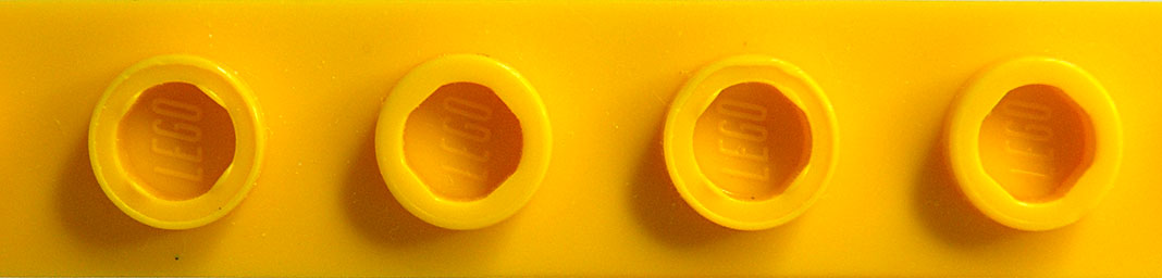
But now look at the knobs of an older part, a classic window:
knob holes, old version
These are perfectly round inside and have much thicker walls: a bar cannot be inserted in the hole. Most knobs have a hollow on their other side, to save on plastic material. That hollow can be moulded easily in parts that are open on one side, but not in windows which have a sill, or in Technics bearing bricks where the bearing is in the way. For these the hollow is made from the top, and the hollow was different in the earlier days. Early holes are incompatible with today’s bars and other ornaments (like flames).
Not so approximate
There are some approximations out there. I examine two cases.
LDraw
Without subtracting from the enormous work that went into the LDraw project and all the merits it has, the LDraw 3D models are approximations. I do not know the reasons for their choices. The LDraw organisation is a fantastic resource for Lego enthusiasts, and the following remarks do not aim to criticise their work. Their goals are also very different from mine.
On page http://www.ldraw.org/article/218 the LDraw Unit is defined. LDraw does not take the play gaps into account, but the LDraw group very wisely uses a unit that is connected to the bricks themselves, not to another unit. They also wisely choose the unit small enough that for all assemblies of bricks, distances can be measured in whole numbers of units (this obviously does not apply to curvy shapes such as animals and accessories for minifigs, but relative distances are not relevant there). The LDraw unit is 1/20th of a design knob distance, i.e. 0.4mm. A plate is then 8 units high (3.2mm), a standard 1×1 brick is 20×20×24 units (8.0mm×8.0mm×9.6mm). This makes the knob 12 units in diameter (4.8mm) and 4 units high (1.6mm).
However, the remark on real world approximations given on that page is wrong: at room temperature 1LDU is certainly exactly 0.4mm, and the value 1/64 inch is certainly wrong. The LDraw brick models will nevertheless work fine between themselves. They are approximations of the real bricks, as I argue below, and in the C4D models I make for myself I also use some approximations.
When looking at 3D models of bricks the obvious element for comparison is the height of the axle hole in the Technics bearing bricks. This is 5.8mm and the LDraw models use 5.6mm instead (as far as I could determine). That leads to small errors, but as stated above, shifting the bearing hole heights only displaces the linked elements but does not cause any strain anywhere because all holes are shifted by the same amount. Look at this assembly made with BrickSmith using LDraw bricks. It is similar to the assembly with the special brick with two bearings arranged vertically:
assembly 1
There is a fair gap between the top of the special brick and the bottom of the plate sticking out over it, which does not occur in reality. That is simply because the holes in that special brick must be spaced 8mm vertically from the bearing brick hole, so they too must be 0.2mm lower, and therefore the gap is larger than in reality. Now stick a 1×6 plate vertically in those holes and you get:
assembly 1 with plate
In this construction I exaggerated the knob height of the plate by a factor of 6 so that the knobs would visibly stick through the bearing holes (and unfortunately also through the plates, but this is virtual stuff anyway). What you see is that everything fits nicely, because the hole in the top bearing beam is also 0.2mm too low down.
Examine another LDraw assembly, of a Technics beam connected to a Technics bearing brick:
assembly 2
The top of the yellow beam is slightly lower than the top of the red bearing brick, and the bottom of it clears the knobs on the plate. This is easier to observe in a frontal view:
assembly 2 from front
Real knobs are 1.8mm high and not 1.6mm as in the LDraw models. But as the bearing holes are at 5.8mm from the bottom, not 5.6mm, in reality too the yellow beam clears the knobs, but its top is flush with the top of the bearing brick, which it fails to be in LDraw.
LDD
LDD, Lego’s own 3D program for building models has a wonderful function for making instructions for anything you build in it. Truly difficult to do, and great work. But some of its parts are wrong.
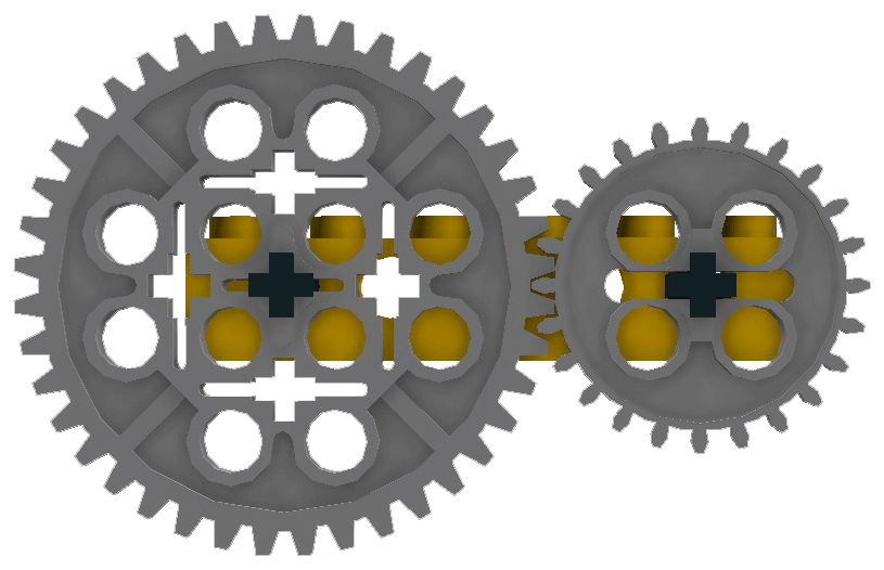
Look at this LDD assembly of a 40 tooth gear meshing with a 24 tooth gear:
two gear assembly from LDD
Both axles are exactly aligned (rotation angle 0º relative to the Technics bearing brick) and the two gears seem to mesh.
But that cannot be so. The teeth on the LDD model of the 40 tooth gear are not like on a real wheel, they are rotated relative to the wheel’s body by half a tooth! Observe the position of the teeth relative to the bars at 45º. Real Lego 40 tooth wheels look like this (though in the image below they are also 3D models):
what real wheels would look like
I aligned the axles also with zero rotation, showing that the teeth would not mesh but overlap. In real Lego one of the axles would have to be turned slightly, the positions would have to be like:
how real wheels would have to be positioned
Now the teeth mesh properly, but the 24 tooth wheel has been rotated by half a tooth, i.e. over 360/24/2=7.5º
That is not much, but anything else fixed to the axles would therefore also be rotated and could not possibly line up in the way it does in LDD. It does not matter which wheel combinations are used, nor how many intermediate wheels are inserted, there will always be some difference in the angles of the axles, and there are cases where this effect is very annoying. It does not occur in Meccano, where a wheel is fixed to a smooth axle by means of a small screw and the angle of any wheel relative to the axle can be determined at will. Lego’s wheels fit on their axles only in four rotational positions (in steps of 90º) because of the shape of the axles’ cross section.
Tradition, Tradition?
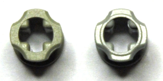
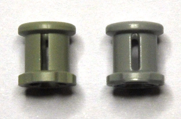
So, to have reasonable play, bricks of n knobs have a width of n×8-0.2mm. A one-knob brick is not 8.0 but 7.8 wide. Now when I wanted to measure the gears and bushings of Technics, I found it very difficult to get good figures. Until I saw that in fact there are two different versions of those parts: old ones and recent ones. The old bushing is 7.8mm high, the new one is 8.0mm.
The two can be distinguished by two visible features, but you have to look closely: one is that the ends of the new ones have slight ridges to add the extra 0.1mm on each end, the other is that the slots in the side are rounded instead of rectangular.
bushing tops (old on left)bushing slots (old on left)
The rounding of the slots is a good idea. Any opening with sharp corners will crack under stress, which explains why slits in leather fittings will end in a round hole to stop the tearing at the end of the slit and why it is easy to break chocolate tablets along the sharp notches. The new bushings with rounded slots will not so easily crack. Indeed, I only ever had two broken Lego parts, and both were bushings: the sides split.
But what happened with the change from 7.8 to 8.0? I surmise that there was a mantra inside Lego: “dimension is n×8 minus 0.2mm”. Thus the person(s) who designed the Technics parts made the bushings and gear hubs 7.8mm high. Out of tradition?
But when you slide gears, wheels and bushings onto axles, you push them together since you have no guiding reference points on the axles. You therefore want them at exactly 8.0mm intervals, to match the Lego grid. Bushings are meant to hold things in place too, so you do not want the 0.2mm play.
Tradition helps doing repetitive tasks with efficiency, but it stands in the way of imagining solutions to new problems. The production dimensions of parts that slide onto axles should firmly be 8.0mm. Someone realised this later on, and the newer parts are 8.0mm.
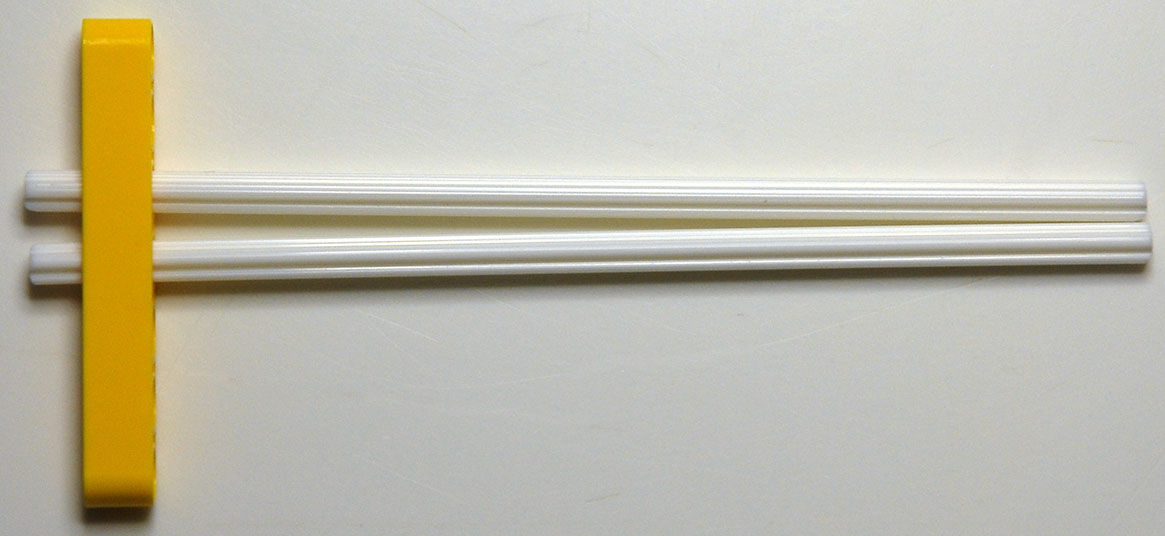
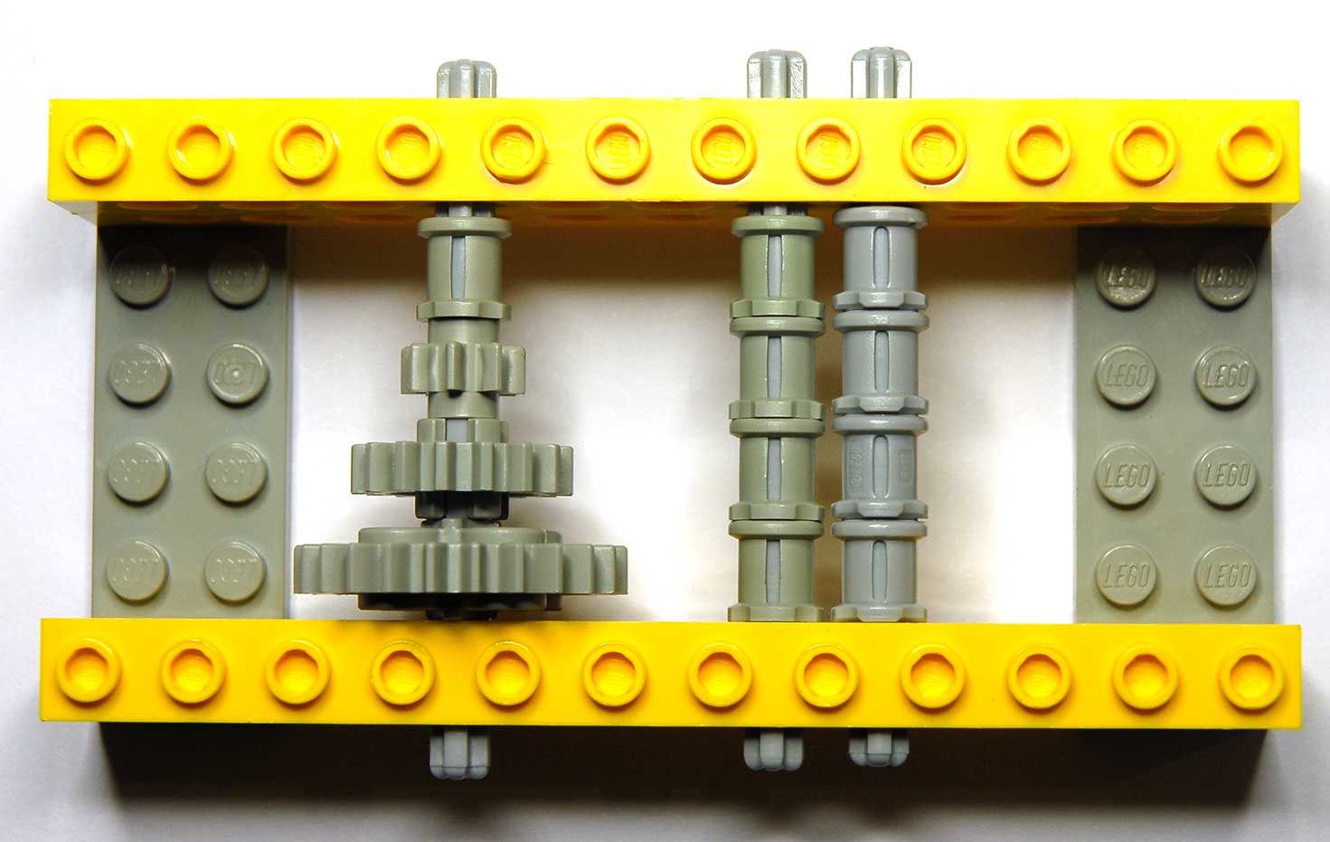
If you do not believe this, examine:
Play gaps on axles
The axle on the left has four old parts on it: a bushing, an 8-gear, a 16-gear and a 24-gear; it leaves a large gap between the top element and the yellow bearing brick. The second axle has four old bushings and also leaves a large gap, while the last axle has four new bushings and only has the 0.2mm gap that is necessary (derived from the fact that the distance between the faces of the bearing bricks themselves is 4×8+0.2mm)
The difference between the rectangular slots and the rounded slots in the bushings is also visible.
If you examine Technics connectors closely you will see that many of them have at least one side that slides on an axle, and that side should be 8.0mm high.
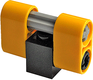
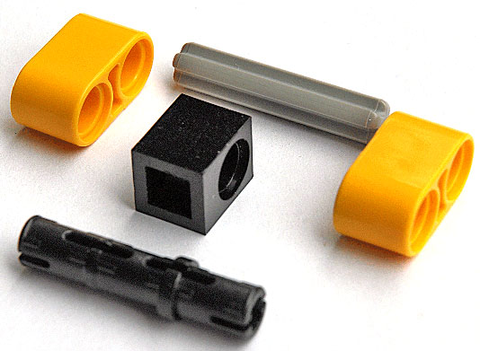
Axle gripping
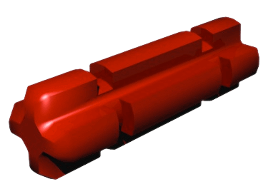
Gears, bushings and connectors grip axles with a fair amount of friction. Some of these parts have small internal “bumps” to provide this friction reliably. They are barely visible:
an axle gripping brick
A close-up:
close-up
with outline
These bumps can be felt when inserting one of the newer type length 2 axles like this one:
axle length 2
The bumps are also very “old” in the sense that even early connectors have them.