For a given pair of gears, and a minimum tooth overlap that must be achieved, which combinations of bricks can be used to position the axles?
Lego gears will usefully mesh when their axles are in positions that are not the simple basic ones. It is not easy to assemble bearing bricks in such a way that the axles are in a useful position: the positions of bricks is determined by the thickness of the bricks and plates under them and the position of their knobs. The calculator makes an example brick assembly for all possible combinations of the common gears and all possible relative positions of their axles. For example:
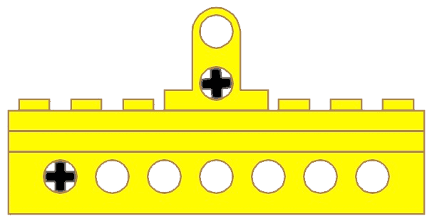
an example of meshing gearsthe corresponding brick stack
This page describes the algorithm of the calculator.
The application can be downloaded in these versions:
A gear wheel has an outer radius R which is measured over the tops of the teeth, an inner radius r which is measured at the base of the teeth ("bottom" in between teeth), and the rolling radius t, which is somewhere in between.
Gears mesh normally when the distance between their axles is the sum of their rolling radii, t1+t2.
This is the case when they are used in the same Technics bearing brick, e.g. wheels of 8&8 teeth, one hole apart (4+4=1x8), or 8&40 teeth, three holes apart (4+20=3x8), and so on.
Practical meshing
Gears also mesh reasonably well when the distance between their axles is somewhat less or greater than the sum of their rolling radii.
Such positions of the axles can occur when the axles are not in the same bearing brick, viz. when the axle of the second gear runs in a bearing that is both vertically and horizontally offset from that of the first. This may be achieved by inserting plates, using special bearing bricks, etc. A certain mechanism may require the axles to be offset in such a fashion, and it may be the only way to mesh two gear wheels when the sum of their rolling radii is not a multiple of 8 (e.g. 8&16 teeth: 4+8=12)
If the distance between axles is not exactly the sum of the rolling radii, the abstract smooth wheels will not touch, but if the teeth of the real wheels overlap sufficiently, the mechanism will function nevertheless and the gear ratio will be the same as in the ideal case since the number of teeth has not changed.
Consider a gear wheel with radii R1, t1 and r1 and another with radii R2, t2 and r2. As soon as the distance A between the axles of these wheels becomes less than R1+R2, some meshing of their teeth will occur; operation will be as designed when the distance is exactly t1+t2, but meshing can no longer occur when that distance is less than the larger of the two values R1+r2 and r1+R2 because the teeth of one wheel will touch the bottom between the teeth of the other.
In practice good meshing only occurs for distances A between R1+R2-D and r1+r2+d where D and d are experimental values.
The value of d is less important than the value of D. I call D the tooth overlap. For the design case, the overlap is R1+R2-(t1+t2) but in general, for a given axle distance A the overlap is
D=R1+R2-A
A good overlap is not too far away from the design overlap.
Analysing the common Gears
Detailed inspection of the common Lego gears shows that the inner and outer radii are not related to the rolling radius in a simple manner: some gears have teeth that are cut deeper, others have thicker teeth that prevent the teeth of the engaging wheel to penetrate to the inner radius, and so on.
The gears we consider here are commom wheels that engage when placed on parallel axles:
Thus we do not consider the small conical gears that are used inside differentials, nor the 14-tooth conical that will only engage with another conical gear on an axle at right angles.
The term bevelled is also used to denote conical gears, but I use only conical in these pages.
The table below gives their characteristics (with as usual all measurements in mm):
type
teeth
d measured
d effective
r
t
R
D
average radius (r+R)/2
t− (r+R)/2
tooth height R−r
factors
normal
8
5.6
5.6
2.8
4.0
4.9
9.8
3.9
0.2
2.1
2 2 2
double conical
12
7.8
8.8
4.4
6.0
6.7
13.4
5.6
0.4
2.3
2 2 3
normal
16
13.6
13.6
6.8
8.0
8.7
17.4
7.8
0.3
1.9
2 2 2 2
end of differential
16
13.8
13.8
6.9
8.0
8.9
17.8
7.9
0.1
2.0
2 2 2 2
clutch
16
13.6
13.6
6.8
8.0
9.0
17.9
7.9
0.1
2.2
2 2 2 2
double conical
20
16.8
17.8
8.9
10.0
10.7
21.4
9.8
0.2
1.8
2 2 5
normal
24
21.4
21.4
10.7
12.0
12.9
25.8
11.8
0.2
2.2
2 2 2 3
crown
24
21.4
21.4
10.7
12.0
12.7
25.4
11.7
0.3
2.0
2 2 2 3
end of differential
24
21.6
21.6
10.8
12.0
12.9
25.8
11.9
0.1
2.1
2 2 2 3
friction
24
21.6
21.6
10.8
12.0
12.7
25.4
11.8
0.3
1.9
2 2 2 3
end of differential
28
25.8
25.8
12.9
14.0
15.1
30.2
14.0
0.0
2.2
2 2 7
double conical
36
33.2
34.2
17.1
18.0
18.6
37.2
17.9
0.1
1.5
2 2 3 3
normal
40
37.4
37.4
18.7
20.0
20.8
41.6
19.8
0.3
2.1
2 2 2 5
turntable
56
53.4
53.4
26.7
28.0
28.8
57.6
27.8
0.3
2.1
2 2 2 7
The number of teeth is an integer whose prime factors are listed in the last column; it is always a multiple of 4.
The rolling radiust in mm is of course always exactly half the number of teeth.
Measuring with calipers gives diameters, not radii.
The inner diameterd as measured is in the first column. However, double conical gears have thicker teeth, preventing those of engaging gears to penetrate completely, and therefore they have been given an effective inner diameter that is larger. As it is difficult to determine exactly how far this penetration goes, there is some uncertainty for this number.
The outer diameterD is as measured.
The radii r and R are just half the values of the effective inner diameter and the measured outer diameter.
Notes on the table
Gears with the same number of teeth can have slightly different radii and therefore should be considered different because their teeth overlap differently with those of others.
The average radius is not the same as the rolling radius, i.e. teeth are not sitting symmetrically relative to the rolling circle. In some cases the difference is as high as 0.4mm.
Tooth height is also not the same for all wheels.
The Axle Grid
Where can the second axle be put relative to the first one? Let the position of the first axle be the origin of a cartesian axes system.
If we make abstraction of symmetry, then we need to examine only positions in the first quadrant: to the right of the first axle and/or above it.
The simplest positions to the right are every 8mm in a normal Technics bearing brick, or an 8mm horizontal step. The simplest positions higher up are at 9.6mm intervals, the height of another brick, or a 9.6mm vertical step.
But we can use plates, so the vertical difference could be a multiple of 3.2mm. In fact, using the special bearing brick we can achieve 1.6mm vertical steps.
There is a 1×1 bearing brick, which makes the possible horizontal step 4mm.
There is a caveat though: while we can put axles at a multiple of 4mm horizontally, the 4mm distance itself is excluded; i.e. we can use n×4mm but n>=2 if the vertical distance is not large enough. Likewise vertically: 1.6 cannot be achieved if the horizontal distance is not large enough. It means there is an area around the position of the first axle where problems occur.
In the position grid shown above the columns are 4mm apart and the rows 1.6mm.
Obviously the origin 0,0 itself is excluded as a position for the second axle. Then the two smallest gears have 8 teeth and their axle distance has to be 8mm or perhaps less, but certainly more than two times the inner radius of 2.8mm, which excludes positions at 5.6mm or closer, even if there were a way to build a brick stack with bearings for those distances.
The two dashed green line arcs indicate the 5.6mm absolutely minimal distance between two 8-tooth gears (inner one) and the normal spacing of 8mm (outer one).
All positions within the inner arc are excluded and marked as filled red dots. The other points inside the outer arc are excluded because there is no combination of actual bricks that would give those close distances.
Position 2,0 is the normal position for two 8-tooth gears.
Position 2,1 would let them mesh but it cannot be built.
Position 2,2 can be built but is an exception in the general calculations because it needs a second 1×1 bearing brick which is not needed in any other case.
Position 2,3 cannot be built.
Position 2,4 can be built but is an exception similar to 2,2.
All other positions can be built, but it makes of course no sense to go further out than two times the outer radius of the largest gear. Hence the grid is limited to indices ceiling(57.6/4)=15 horizontally and ceiling(57.6/1.6)=36 vertically.
Note: although 2,4 can be built, there is at present no gear pair that would mesh with that position; it is too far from the first axle for two 8-tooth gears and too close for anything else.
Note: there is a way to achieve 2,1 by using the special vertical brick in a plane behind the normal brick stack and lowered, i.e. in fact position 2,(-1).
General Approach
Choose a pair of gears, and choose a minimum tooth overlap that must be achieved. Which combinations of bricks will position the axles such that the gears mesh?
For each point i,j of the axle grid we can compute the distance to the first axle:
For a given pair of gears we know the minimum and maximum axle distances to achieve a specified minimal tooth overlap.
-- The shapes of bricks forbid getting two holes close together in some cases.
<p> -- For example, having the second bearing hole only 1.6mm up from the first is impossible because</p>
<p> -- it would simply overlap with the first. There are a few other cases. Given the bricks we use,</p>
<p> -- a hole can always be put at 12 or more horizontally and at 9.6 or more vertically.</p>
<p> -- Within the rectangle of 8mm or less horizontally and 8mm or less vertically, there are only</p>
<p> -- five hole positions of the 6x3=18 table that can be built.</p>
<p> -- They are:</p>
<p> -- horizontally 8, vertically 0: very normal.</p>
<p> -- horizontally 8, vertically 3.2: needs a second special horizontal brick on a plate.</p>
<p> -- horizontally 8, vertically 6.4: needs a second special horizontal brick on two plates.</p>
<p> -- horizontally 4, vertically 8: can be computed normally(*), but it actually does not work(**)</p>
<p> -- horizontally 0, vertically 8: can be computed normally.</p>
<p> --</p>
<p> -- * "can be computed normally" means that the vertical bricks are computed first, then the top brick</p>
<p> -- is put in the desired horizontal position.</p>
<p> -- ** the teeth on the 8-tooth wheel are so far apart and there is so much play in the bearings that</p>
<p> -- the teeth of the other 8-tooth wheel pass without touching although there is sufficient overlap</p>
<p> -- and at some positions the teeth touch.</p>
<p> --</p>
<p> -- For this pair:</p>
<p> -- the maximum distance between their axles is that at which the teeth no longer</p>